
A cold solder joint is the failure mode that production teams blame on operators when it’s almost always an equipment, process, or material problem.
The visible signs are familiar: dull, grainy joint instead of a shiny meniscus; weak fillet that fractures under thermal cycling; intermittent electrical continuity that passes ICT but fails in the field three months later.
What makes cold joints particularly costly is that they often pass first-pass inspection. They show up at the customer. They show up in warranty returns. They show up on the FA report from your Tier-1’s quality team — and by then, you’re already shipping.
This article walks through the seven real root causes of cold joints in production environments. For each, the diagnostic signal, the underlying physics, and the fix you can implement on the bench tomorrow.
What “cold joint” actually means
Before the causes — the definition. A cold solder joint is one where the solder has not fully wetted to one or both metal surfaces. The intermetallic layer (the alloy zone where solder bonds to copper / nickel / tin) is incomplete or absent. Mechanically, the joint is weak. Electrically, it has higher resistance than a properly-formed joint, and that resistance can drift with temperature.
Visually, a cold joint typically shows:
– Dull, matte, or grainy surface (good joints are shiny — even with lead-free, which is naturally less glossy)
– Convex bulge instead of concave fillet
– Solder sitting on top of the pad rather than wetting into it
– A visible “ring” where the solder didn’t flow over the pad edge
These signs are usually multiple — one alone can be misleading. Look for two or three together before calling it a cold joint.
Cause 1 — Insufficient temperature at the joint
The most common cause, and the one most often misdiagnosed.
The setpoint on the station says 350°C. But the actual temperature at the joint is rarely the setpoint — it’s setpoint minus the heat sink the joint represents. A 3 mm copper pad pulls 30–50°C out of the tip in the first second of contact.
If the station’s closed-loop control is slow (typical of older or budget stations), the tip never recovers to setpoint during the joint formation window. Solder partially melts but doesn’t flow.
Fix:
– Verify your station holds ±2°C under load, not just at idle. Many stations spec’d as “temperature-controlled” actually drift ±10–15°C when touching thermal mass.
– For ground planes and large pads: pre-heat the bottom side of the PCB to 100–120°C with a bench preheater. Reduces the thermal demand on the iron.
– For lead-free, set 360–380°C, not 350°C — the alloy needs the headroom.
Cause 2 — Insufficient dwell time
Solder needs about 2–3 seconds of contact between liquid solder and the pad/lead surface for the intermetallic bond to form. Operators rushing through joints — typical when production targets are tight — produce joints that look finished but have incomplete wetting underneath.
Diagnostic signal: consistent cold joints across one operator’s shift. Other operators on the same equipment produce good joints.
Fix:
– Don’t fix the operator — fix the cycle time. If the production target requires 1-second-per-joint speed, the soldering process won’t physically work. Either invest in faster equipment (production-grade station with quick recovery) or extend cycle time.
– Train operators to watch the solder visually — joint is done when the fillet shines and the meniscus is concave, not when the timer beeps.
Cause 3 — Wrong tip geometry
Heat transfer is dominated by tip-to-pad contact area, not by tip temperature. A fine conical tip on a large ground-plane pad transfers heat poorly, regardless of how high you crank the temperature.
We see this most often in benches that use 2–3 default tips for everything. The fine tip that’s perfect for 0402 SMD is wrong for through-hole bus connectors. Cranking temperature compensates for poor contact area in the short term but oxidises the tip rapidly and produces inconsistent joints.
Fix:
– Match tip geometry to component package (see our tip selection guide for the full matrix).
– Stock at least 5–6 distinct tip geometries on a production bench.
– Train operators to change tips for different jobs — yes, this takes 30 seconds per change. It saves minutes of rework per shift.
Cause 4 — Tip oxidation / poor tip condition
A clean, tinned tip transfers heat by direct metallic contact. An oxidised tip has a thin insulating oxide layer that drops effective heat transfer by 40–60%.
Operators see the symptom (bad joints) and turn up the temperature, which oxidises the tip faster, which produces worse joints. The compensating spiral.
Fix:
– Use a brass-wool tip cleaner, not just a wet sponge. Wet sponges thermal-shock the tip and accelerate corrosion.
– Re-tin the tip every 5–10 minutes during heavy use. A drop of fresh solder on the tip face restores the wetted surface.
– Replace tips when the wetted area shrinks below ~70% of original. A worn tip costs ₹150 to replace; rework costs ₹500–2,000 per failure.
Cause 5 — Flux activation problems
Flux’s job is to remove oxide layers from the metal surfaces in the moment before solder wets. If the flux:
- Has expired or dried out (rosin flux)
- Was applied unevenly (gel flux)
- Activated at wrong temperature (wrong flux type for the alloy)
- Didn’t have time to activate before solder arrived
…then oxide remains. Solder doesn’t wet. Cold joint.
Flux activation is a particular problem with lead-free soldering — the higher temperatures degrade flux faster, and many operators were trained on leaded systems where flux was forgiving.
Fix:
– Use no-clean flux suited to your alloy (lead-free needs higher activation temperature flux)
– Apply flux before the iron touches, not after — flux works at 150–200°C, well below solder melt
– For wave-prep / dip work, monitor flux specific gravity and replace per manufacturer interval
– For hand soldering, fresh flux pen on every shift change
Cause 6 — Surface contamination on pads or leads
Even with perfect equipment, perfect tip, perfect flux — if the pad surface has oils from human handling, residue from prior reflow, or oxidation from extended storage, solder won’t wet.
This is a contamination problem masquerading as a soldering problem.
Diagnostic signal: cold joints concentrated on specific board lots, specific component reels, or specific pad types. Other identical work passes fine.
Fix:
– IPA wipe pads before hand soldering, particularly for boards stored more than 3 months
– Verify component leads aren’t oxidised — lead-free finishes can degrade in storage; tin pre-tinning helps
– Climate-control storage areas: < 60% humidity, < 25°C
– Use HASL or ENIG board finishes for components with long shelf life
Cause 7 — Mechanical movement during solidification
The solder transitions from liquid to solid over a temperature range (250–217°C for SAC305 lead-free, 188–183°C for tin-lead). If the joint moves during solidification — operator hand tremor, board flex, vibration from adjacent machinery — the solidifying alloy fractures into a granular structure with no proper crystalline bond. This produces a classic dull-grey “disturbed” joint that is mechanically and electrically weak.
Fix:
– Stable bench. No vibration from adjacent presses, conveyors, or HVAC.
– PCB held in fixture during hand-soldering — not by hand
– Operator wrist support
– Train operators to pull the iron away cleanly after the solder melts, then keep the part still until solidification — typically 1–2 seconds visible “shimmer” on the joint surface
A diagnostic checklist for production teams
When cold joints start appearing, run this triage in order:
- Visual: which joints are cold? All joints, one operator, one component package, one PCB lot? Pattern tells you cause class.
- Thermal: is the station holding setpoint under load? Probe the tip temperature with an external thermocouple under contact load.
- Tip: is the tip clean and well-tinned? Visual inspect; replace if worn.
- Flux: is flux fresh, applied properly, suited to the alloy?
- Surface: are pads contaminated, oxidised, old? Check storage age and visual oxidation.
- Process: is the cycle time physically allowing 2–3 sec dwell?
- Mechanical: is the bench stable, the board fixed, the operator supported?
In our experience, ~70% of cold-joint problems trace back to causes 1, 2, and 3 (temperature, dwell, tip). Equipment fixes solve most of these. The remaining ~30% are flux, contamination, and process — all material/training issues.
A free 1-page checklist
We’ve packaged this triage as a printable A4 PDF — keep it next to the bench. Free, no signup wall.
📎 Download the cold-joint diagnostic checklist (PDF)
Equipment that helps
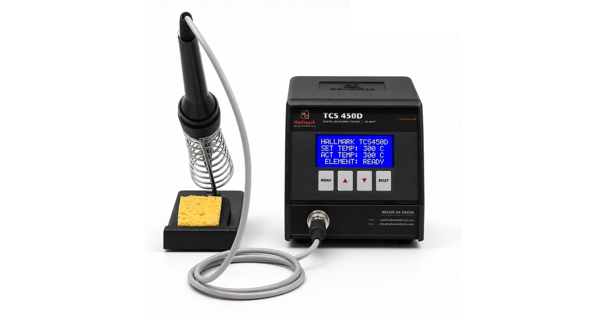
If you’ve worked through the checklist and the root cause is “the station can’t hold setpoint under load”, that’s a station problem.
Hallmark’s TCS 450 Digital is a 450W microprocessor-controlled station that holds ±2°C under load — engineered exactly for the production-floor problem this article describes. Made in Pune since 1987, with same-week spares dispatch.
If you’d like a spec sheet or a 2-week demo unit at your facility, drop us a note and we’ll route it to the right engineer.
Related guides on Hallmark
- Weller & Hakko alternative in India — TCO compared
Imported vs Indian soldering station — when each genuinely wins. - How to choose a soldering station — 2026 buyer’s guide
Wattage, stability, ESD, tip range — what an Indian procurement team needs to know. - Imported vs Indian soldering station — real 5-year TCO
Worked numbers, downloadable spreadsheet, an honest method. - BGA rework without lifting pads — technician’s playbook
6-step bench protocol that protects pads — preheat, profile, air, prep.